.jpg)

Everything about PIR & Simple Circuit
Everything about PIR
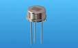
PIR or Pyroelectric Infrared Sensor has motion detecting duty of a human or animal body.
PIR won’t detect a stationary infrared source. It is very sensitive to changes air density & might be produce false responses if you don’t use a special lens of PIR.
The detection range in normal mode is about 0.5 m but can extended to more than 8 m with a lens.
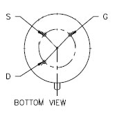
Most of PIRs have 3 pins. D, S, GND.
D connect to VCC
S is Output
GND Connect to ground.
PIR with 3 PINS:
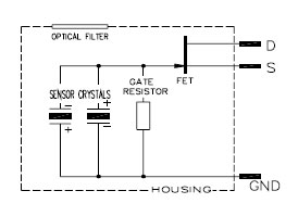 & about 4 Pins PIRs I must say pin 3 & 4 is connect to ground.
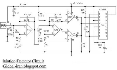
Here is a simple circuit.
This circuit is a good choice for alarm systems with adjustable sensitivity.
 Amplifier:
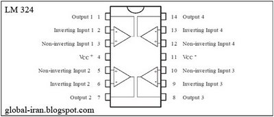
LM324 or same 324.
When motion is detected the sensor output will transition a very small voltage transition at pin 2.
This voltage will amplified many times to do the job.
The output signal at pin 2 is bypassed to ground by a 100pf capacitor to shunt any RF energy picked up from radio transmitters.
Sensor pin 2 feeds into the first stage amplifier IC1A at non inverting input pin 3.
That amplified voltage does not have enough power to run our comparator. A high pass filter connects from Pin 1 (IC1A Output) to pin 2 & a high pass filter C2, R3 connects from pin 2 to ground. These networks set the amplifier to amplifies only signals above DC & below about 10 Hz.
The output of IC1A feeds into the second amplifier stage at pin 6 through R5 & C4.
A feedback network connects from IC1B output to inverting input pin 6.
R8 is a potentiometer and installed to adjust sensitivity of the sensor. That controls the amount of feedback.
Remember: The non inverting input of IC1B biases to ½ of supply voltage or 2.5 v for this circuit. Check out your circuit & if it is not about 2.5 v change R6 & R7 value to gain 2.5 v.
Pin 7 output is 2.5v when no motion is being detected. The output of IC1B feeds into IC1C & IC1D.when an operational amplifier use as a comparator its output switches at a full up or full down when one input is just a few millivolts higher or a few millivolts lower than the other. The purpose of this comparator is to provide a very small voltage centered around 2.5 v.
Remember: Make sure that the pin 5 is 2.5 v & pin 9 & pin 12 are about 2.5 v.
Output of IC1C & IC1D goes to a logical OR gate made of Diode 1N4148 OR 1N914.
IC1C will not turn on until pin 10 goes more positive than pin 9. & IC1D will not turn on until pin 13 goes more negative than pin 12.
When motion is detected the output of second amplifier stage must to IC1B go more than 175 millivolts 2.5 v or must to go less than 175 millivolts about 2.5 volts to turn IC1C & IC1D on. This amplifier & comparator will therefore respond to both positive & negative transitions from output pin 2 of sensor.
Remember: Make sure input pin of IC1A pin 3 is not more than 450 millivolts changing R1 & R2 Values can help to adjust the input voltage.
Timing Circuit:
CD4538 two precision Monostable Multivibratur
The purpose of CD4538 in this circuit is getting a signal & save that until adjusted with R10 & C6.
R10 KOhms × C6 mf = 4538 ON Time
Output of IC1C & IC1D feeds into non inverting pin 4 of IC2. R9 pull down resistor connects from cathodes D3 & D4 to Ground. Pin 8 is GND. & restart pin, pin 3 connects to VCC. 4538 input at pin 4 must be between 0.5v & VCC + 0.5v. Inverting pin, pin5 connects to VCC. Pin 16 is VCC. Output of IC2 Pin6 has enough power to drive a normal LED.
Enjoy.
Help me with your comments.
MAB September 2006
mabiran@gmail.com